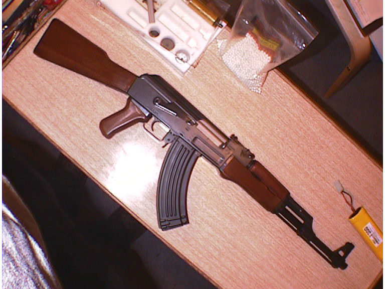
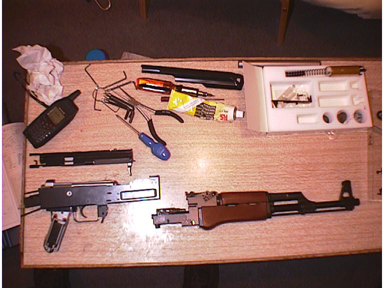
Well as a
stock rifle, the AK is fairly boring. It's only fair to fit a Systema Power
FTK (Full Tune-up Kit UK Level 1), so it was decided
to buy and fit one. Again, as with much of our equipment, it was bought from
WolfArmouries .
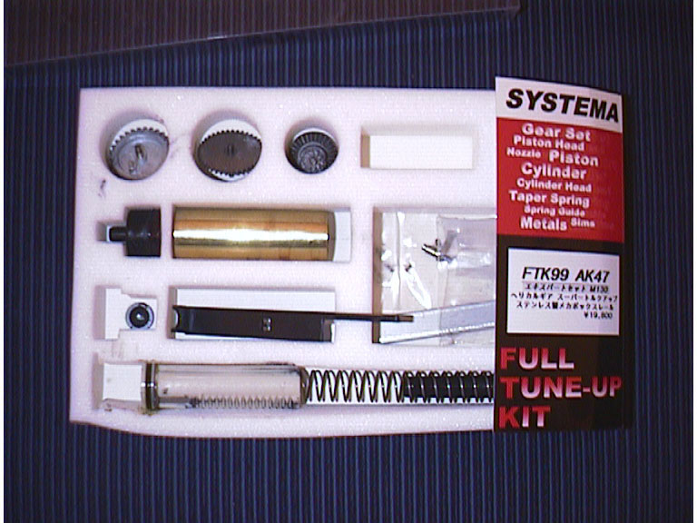
The Systems FTK includes:
new cylinder
and cylinder head
new piston
M100 Spring
new spring guide
rod
new gearbox end
(the snap-on sheet that holds the two tops of the gearbox sides together)
6x new metal
bushings
new nozzle
3 new helical
gears
2 washers (for
the drive gear)
new non-return
lever and return spring
valve movement
lever (black plastic about 3 inches long)
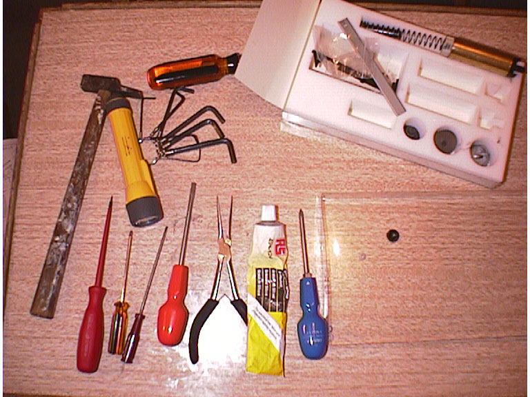
You'll need these
tools: philips/flat head screwdrivers, allen keys, torx bit set, long-nose
pliers, silicon grease, tac hammer and a small torch
IMPORTANT:Please note, this article is correct to the best of my knowledge. Taking
a gearbox to pieces, and upgrading it, is the most complex thing that
you can do to an airsoft weapon. If you are not confident that you know what
you are doing, I'd recommend that you consult someone who is, and get them
to either aid you, or watch over you as you do it for the first time. This
website, and it's members will not be held responsible or liable for damage
to anyone or anything resulting from information or advice contained herein.
Please
note that this is only the first draft of this guide, as such,
it will be upgraded and updated regularly when I have the chance. The information
has yet to be verified and proof-read, so they may be errors in the following
text.
Part 1 - Stripping
the rifle
The first thing
to do is to remove the stock, and the magazine. To remove the stock,
remove the but-plate, take the battery out of the stock, then, simply
undo the 2 screws on the underside of the stock. Remove the stock, and
set the hop-up on the rifle to zero, or the minimum setting.
When you get the
stock off a few centimetres, you'll notice that there is an electrical
cable passing through the join. Simply unplug this cable at the connection
that you find as you pull the stock away from the receiver.
You should then
remove the top cover (covers the battery). This can be removed by simply
depressing the sprung button at the rear and lifting the cover up.
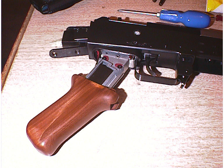
Next you should remove
the pistol grip cover.
Unlike other AEG's
such as the G3 or MP5 the screw on the bottom holds the cover on, rather
than setting the gearbox pressure on the motor.
As you take the screw
out you can just slide the grip off pulling it away from the rifle body.
The next task
is to remove the top receiver cover, that holds the cocking handle,
and the dummy battery cylinder. If you have an AK with a folding
stock (the AK47s), this will hold your battery, rather than a
dummy cylinder.
The top cover
is held on by 2 screws, this is at the front left of the cover,
it's tiny, with a philips head.
The other
screw that should be removed is the hop-up adjustment handle,
this is the piece of plastic that you move back and forth to adjust
the hop-up. This is hidden behind the cocking handle. You'll need
to hold the cocking handle back, and then remove the screw that
holds this tiny piece of plastic on.
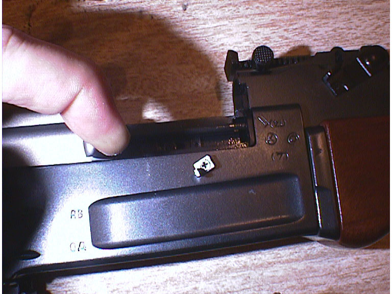
The final
part to undo, to get the top cover off, bar that provides the
spring action for the receiver cover button. This is a piece of
steel (a long bar about 5mm in diameter) that runs the length
of the top of the receiver.
This is located
in the back of the metal button you push to release the top cover.
To get the spring out, simply use a flat-blade screwdriver and
pry the spring out.
The button
won't go anywhere when you detach the spring, as it is attached
to the gearbox in a enclosed slide. The button will come out later
when you separate the sides of the gearbox.
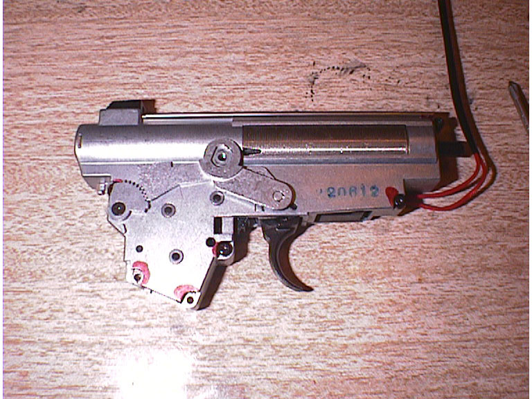
The top half of the
receiver simply slides back (towards where the stock goes), then it comes
off upwards. This should leave you with the top of the gearbox exposed.
Please note at this
point the position of the red wires. It is important that when the gearbox
is placed back that all the wires go back to where they came from, and
are not pinched by the sides. Position of the sling point that you can
see on the side of the rifle, should also be noted. The clip is held in
with an 'L' shaped piece of steel that will fall out the second you turn
the rifle upside down. So watch out for it.
The piece of steel
sits inside the plastic of the lower receiver shell, and stops the sling
clip pulling out of the side of the rifle.
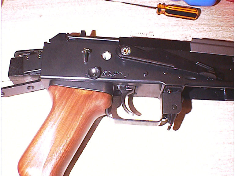
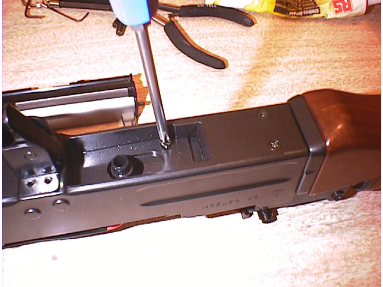
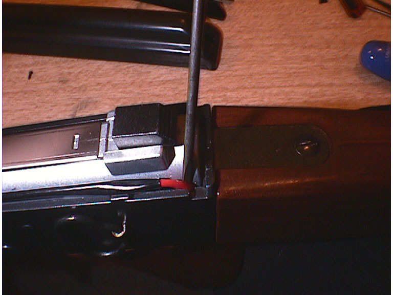
In order to extract
the gearbox from the receiver there are a few things that need to be done.
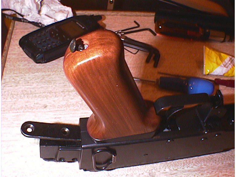
Firstly the fire-select handle needs to be removed.
This can be done at
any time before the gearbox is removed. I actually removed it before the
top of the receiver, as you can see in the photo.
The handle is held
on by one philips screw. To get to the screw, simply pry off the steel
cap that covers it with a sharp-ish flat-blade screwdriver. When the cover
is off, simply undo the single screw and take the handle off.
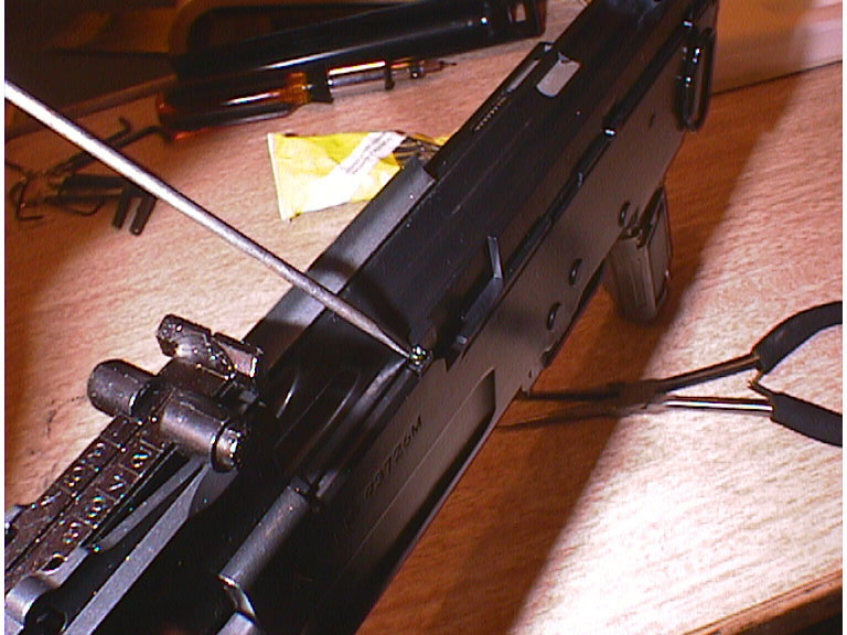
The next thing to
do is to separate the 2 halves of the rifle, the receiver and the barrel
assembly You should be able to see the join, which is just behind the
top backsight. Unlike the G3 the gearbox needs the rifle to be separated
from the hop-up unit before you can take it out of the receiver case.
To separate the 2
halves is a fairly simple process, but should be done carefully as the
hop-up mechanism is fragile, and any damage to the rubber 'O' ring inside
it would be fairly expensive (for what it is), and fiddly to fix.
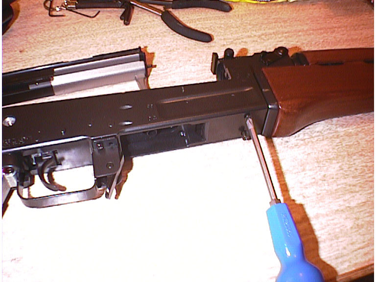
It's important to
support the rifle as you take the four screws out. You do not want the
weight of the rifle to bend the join between the two parts.
To take the 2 halves
apart, locate the 4 screws on the underside of the rifle, between the
trigger guard and the foregrip.
Two of them are recessed
into the area when the magazine locates itself, near the bb entrance to
the hop-up. The other 2 are located near the foregrip. You'll need a number
2 philips screwdriver to remove these 4 screws.
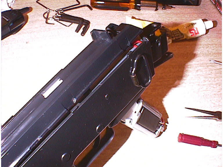
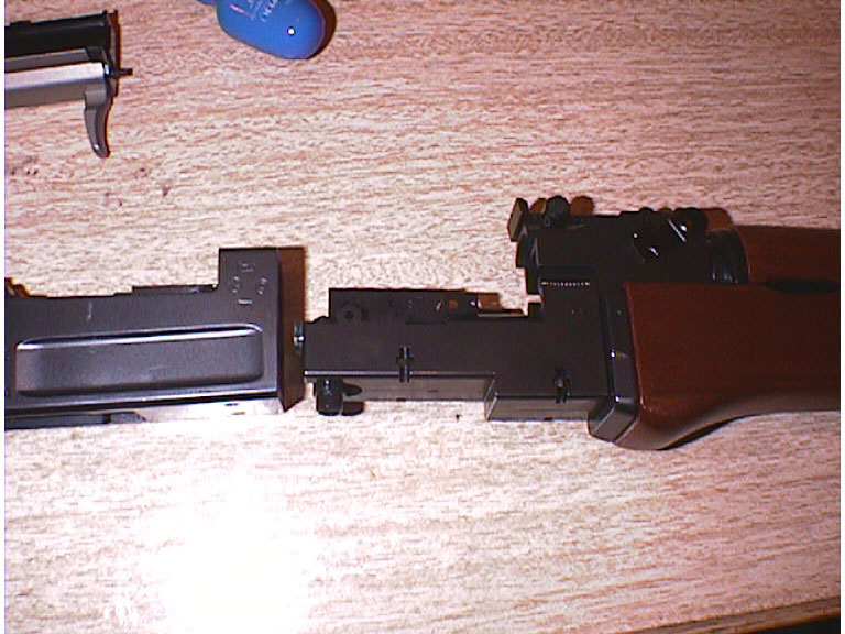
When all 4 screws
have been removed, you can carefully pull the 2 parts away from each other.
This will leave you with the 2 parts as is in the picture to the left,
with the gearbox on the left and the hop-up on the right.
You can put the barrel
assembly to one side, as it's not needed until you begin to reassemble
the rifle after you have finished working on the gearbox.
Now, to remove the
gearbox from the receiver housing, you will need to remove the four screws
located on either side of the steel bracket that the butt was attached
to.
When these screws
have been removed you should be able to carefully slide the gearbox out
of the casing. It might be a little tight, as the trigger will touch the
case as you pull the gearbox out. Simply depress the trigger in a firing
motion and the gearbox should come out easily.
Part 2- Disassembling
the Gearbox
This is possibly
one of the more difficult tasks to do, on the disassembly side of things. One
of the problems of taking a gearbox to bits is that there is a highly compressed
spring running across the top inside the chassis. With an AK gearbox, this spring
is held in place at one end by the cylinder (the brass tube), and at the other
by a rectangular piece of metal, that is secured into two holes on either side
of the gearbox chassis. This spring will fly out, given half a chance.
As a precautionary measure, make sure that there is nothing breakable behind
the motor end of the gearbox (the end that doesn't fire) like your eye or your
friends head - this is the end that the spring will fly out of if you are not
careful.
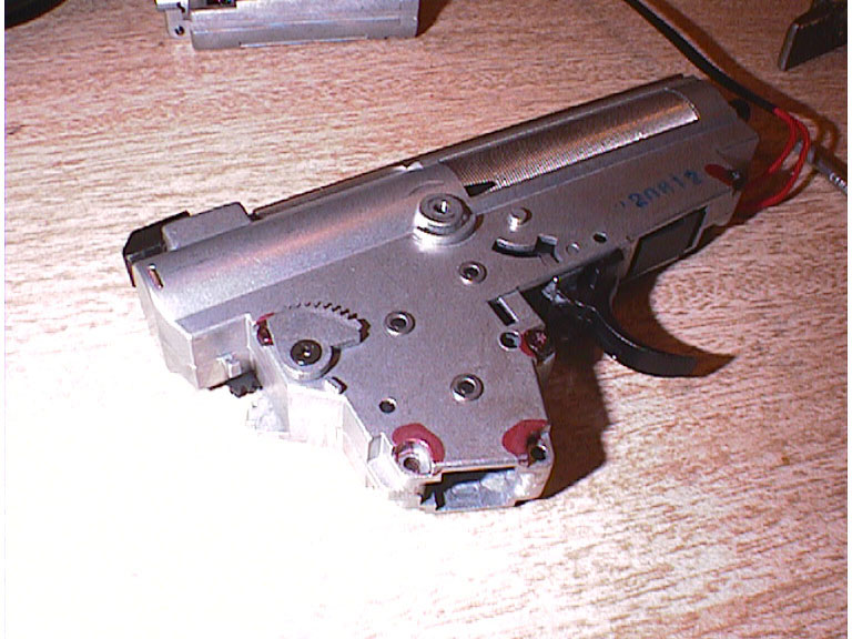
Before
you can get into the gearbox you'll need to remove the gear assembly that
controls the fire-selector lever, from the outside of the gearbox, and
detach the motor.
To detach
the motor, simply remove the 2 screw at the corners of the metal frame
that holds the motor. When you have removed these screws, simply carefully
pull the motor away from the gearbox, and set the motor to one side.
The motor
will still be attached to the gearbox by the electrical cables that are
attached to the firing circuit, so make sure that you don't pull the wires
around too much, as you might sheer the points where the cable is soldered
to the motor.
Before
removal
After
removal
Now
you must take off the 'fire-select' assembly. This is made of 4 pieces of
metal. There are 2 parts on one side, an 'L' shaped piece of metal, and
an 'A' shaped piece it connects to and sits on. The 'L' shaped piece can
be removed by undoing the screw that you can find in the centre of it. The
'A' shaped piece is merely held in place by a pivot, so it should come off
very easily.
Don't worry too much
about the position of the parts, they are all handed, and it's fairly
simple to make sure that you get them together correctly when you come
to reassembling the lot afterwards.
Of the rest of the
assembly, 2 parts comprise a pivot that runs through the gearbox from
one side to the other (held together by a single black screw). Remove
the black screw, and you should find that the pivot comes into two pieces,
with one part on either side.
Please
note the placement of the metal gear on the side, into the black
plastic rack.
To gain entry
to the gearbox, you'll need to separate the two halves of the chassis. First
you should remove the large piece of steel clipped over the top of the gearbox.
You simply slide it towards the valve end of the gearbox, using a flat blade
screwdriver. Don't worry too much if you bend it as there is a reinforced replacement
part in the Systema kit - obviously it's better to keep it in good nick though.
After you have
safely removed the top cover, carefully remove all the screws on the outer edge
of the gearbox. You should find that some screws are torx heads, and some are
philips head. When you remove the last screw, the 2 sides of the gearbox should
stay together, as they are a very tight fit, they may not so, so be careful
that you keep the gearbox on a level flat surface, so that nothing can roll
out. To ensure that the gearbox doesn't 'explode', keep a firm and constant
pressure on the brass cylinder, it's normally easier to get a friend to do this
for you while you undo the screws.
When
all the screws have been removed, you'll need to remove the black plastic
cover that's behind the trigger, this covers the edge of a gear that sticks
out the side of the gearbox.
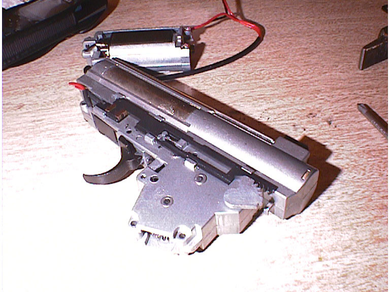
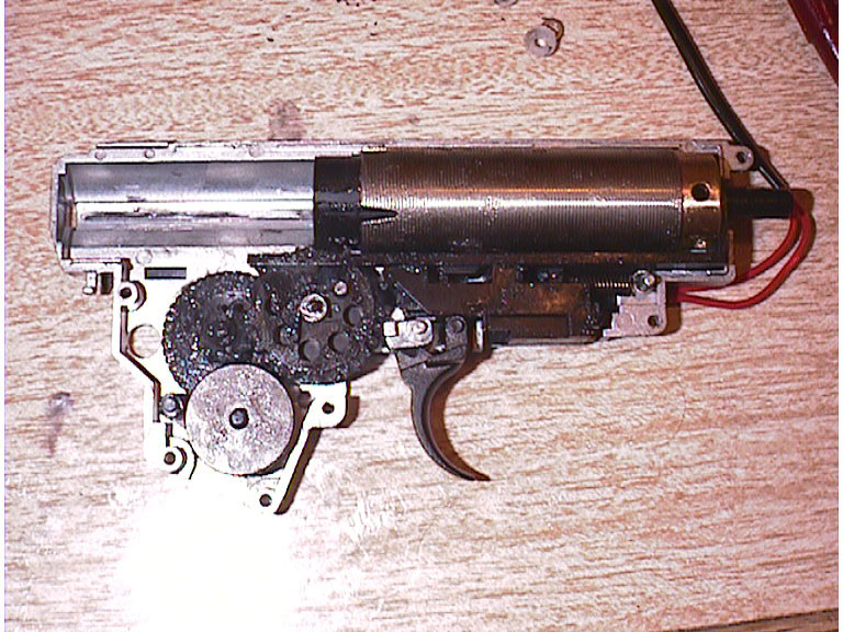
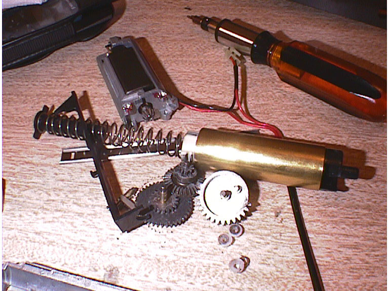
Now for
the real tricky bit. You need to carefully pry the 2 halves of
the gearbox apart, while not allowing the spring to get too loose. I use
a fairly sharp screwdriver, lifting the 2 sides apart from the bottom,
near where the motor connects. When the 2 shells are almost free of each
other I put my finger inside (if there's room) or another screwdriver
to hold the end of the spring in place.
If all
goes well you should end up with something that looks like the photo to
the left.
Part
3- Fitting the Systema Parts
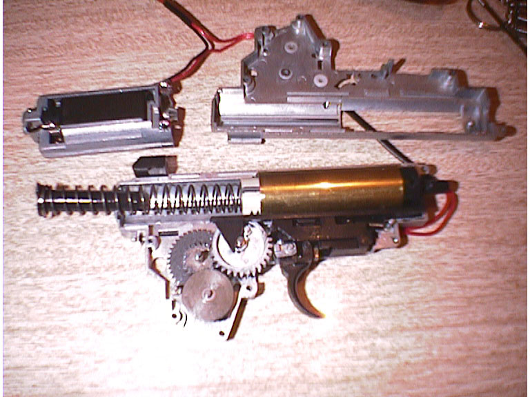
The first thing to
do is to remove the piston/spring/cylinder set. This is the brass cylinder,
and the white piston inside it, with a spring attached.
There will be plenty
of grease around, all over the gears and on the cylinder, so I'd recommend
keeping a roll of kitchen roll handy, to wipe it off your hands, as it
makes it very difficult to handle things.
The brass cylinder
will have a black plastic nozzle attached to the end, and a long plastic
lever along the bottom of it. Keep the black plastic nozzle handy, you'll
need to put it back later.
You can now remove
all 3 gears from the gearbox, and place them to one side. You won't need
them, as they will be replaced.
On the underside of
the lower of the 3 gears you'll find a small spring loaded leaver, note
it's position (including the spring) then remove it, as this too is
replaced by a better Systema part.
The next thing to
replace are the bushings (there are 6 of them). These are basically bearings,
that the ends of the gears revolve in. The replacements are metal, whereas
the originals are nylon, and simply not up to the job of higher speed
and power -they melt if used with advanced gearing. Simply 'punch' out
the old ones and snap in the new ones.
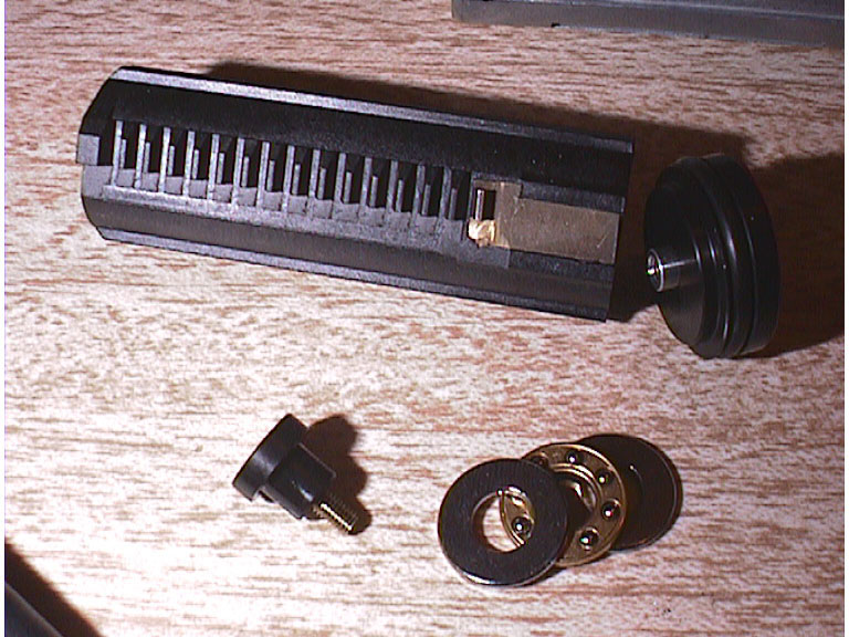
Now is a good time
to construct the piston. For some reason Systema ship this kit with the
piston in parts (unlike a G3/MP5 kit). The piston consists of a piston
head (red faced), a piston, a screw mounted in a black plastic end, 2
washers and a 'ball-bearing race'.
You'll need a bit
of patience to do this and a long No2 philips screwdriver. Now take the
black plastic piece with the screw in it, thread a washer, the ball-race
then a washer over the end of it. The idea is to screw the 3 washers,
onto the inside of the piston, through the small whole at the end and
into the piston head, which is outside.
It's a real bummer
to do, as you need to balance the lot on the end of a screwdriver inside
the piston, and then screw it onto the pistonhead outside.
Make sure you screw
this in fairly tight, you don't want the piston head coming off while
in use, as that will make a mess.
Good luck.. it took
me 5 attempts to get it right.
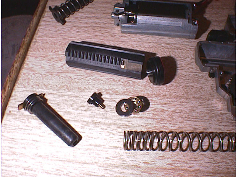
When that is done,
u can place the new spring, inside the piston (it'll butt up against the
washer assembly you have just screwed inside). Then you place the guide
rod end into the other spring end (i.e. the one not in the piston).
Now the next
bit is fairly complex so I'm going to rely on a few pictures, much more than
normal, to show you what I mean.
There are 3
gears to put in and a small non-return lever with a spring on it.
Assemble the
cylinder set, this is made from the ribbed cylinder, and the solid brass end.
The brass end needs coating in silicon grease where it will touch the cylinder,
and around the rubber grommet. Then place the brass end inside the end of the
cylinder that does not have a flared end.
Now for an
important bit of information: In the Systema FTK there would have been a bag
with 2 teenie tiny washers in it. Carefully open this bag, the two washers are
of different sizes, one is larger (and thicker) than the other.
(The following
directions are in relation to the gearbox images shown below) The small washer
goes on the top of the main drive gear (this is the one that drives the piston)
. The large washer goes on the UNDERSIDE of the main drive gear between the
gear, and the new metal bushing you recently put in. This washer needs to go
under a small lever you'll find there, simply slacken the black screw that holds
the lever down, slide the washer under that lever, then tighten the screw back
up; but make sure that the lever can still pivot easily, so don't over tighten
it.
Before the next set
(the adding of the gears) you need to grease EVERY moving part with silicon
grease.
The bushings need
plenty of grease too, as do all the contact points where the gears either
touch, or get close to each other. Don't worry about the mess the more
grease the better (within reason).
Coat the inside of
the new cylinder with grease, and the piston head, the nozzle and the
piston itself - specifically the gearing on the piston side where the
drive gear will mesh with it.
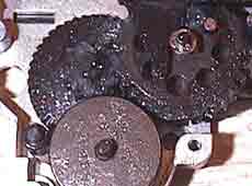
The first
gear to put in is the one that goes in the middle (large flat and thin),
place it with the large flat side to the bottom. The next thing to add
is the spring loaded non-return lever, exactly as the original was., While
holding this back, place the next gear in (the one without holes in its
side).
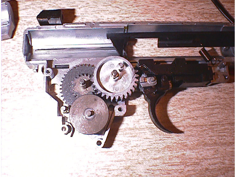
The last
gear to add is the main drive gear, this should be inserted as shown in
the picture, in this EXACT position. In this position its just ready to
draw the nozzle back, via the large black lever, and pull the piston back.
When
you are certain the gears are in, turn them (they'll only turn one way)
a few revolutions to make sure that the gears are free. When you are sure
that they are free moving (there should be very little resistance) set
them back so that they are in the same position as the image to the left.
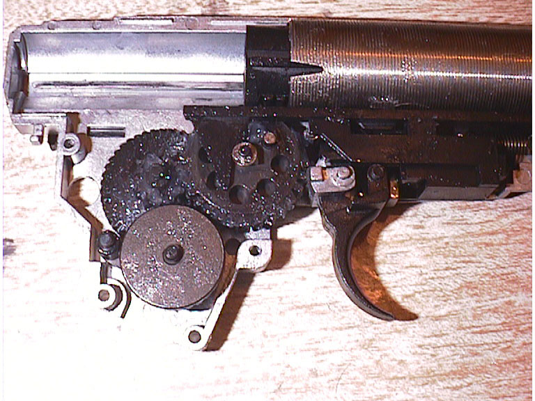
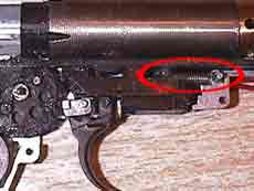
Now you have all the
gears in the correct position, you need to put the replacement cylinder
and piston set in, after you have attached the new nozzle movement lever,
and the return spring that goes with it. You can see the return spring
circled on the image to the right in red. This spring is attached to the
gearbox by a protruding pin, and to a leg on the nozzle arm.
The black nozzle arm,
attaches to the black nozzle (small back cylinder) and goes over the end
of the new cylinder end (the brass cylinder with a hole in each side).
In this position, when you move the arm back and forth the black plastic
piece should move back and forth in turn over the brass pipe.
You should find that
the head of the cylinder fits nicely into the gearbox, and that a protrusion
from the gearbox face, fits into a hole on either side of the brass nozzle
end.
With the cylinder
in, you can place the spring, with guide end, into the end of the piston
- obviously the guide rod, goes at the opposite end to the piston.
Now comes the difficult
part, you need to compress the spring, and locate the guide rod end
in the hole at the back left of the gearbox (you should see a thin rectangular
hole where you poke the metal protrusion from the guide rod.
It takes a bit of
practice, but it's easiest if you keep the cylinder held down onto the
gearbox with a spare thumb, otherwise it may fly out if the spring breaks
loose and/or slips.
It's normally easier
to handle the spring, after you have cleaned your hands of silicon grease.
=)
When the spring
is in the right place, you can attempt to place the other side of the gearbox
on, while holding the spring down. It'll take a bit of tweaking, as the gear
axles need to be located in the correct holes, as does the cylinder etc., so
you may need to poke a sharp thin screwdriver in to poke things into the correct
place.
When the 2
sides are together, fit the screws, and secure the 2 sides together, then attach
the replacement top cover for the gearbox, and slide it on, from the cylinder
end first. I found I had to tap mine (LIGHTLY) with a small tac-hammer
to get it to slide on. You may wish to grease it a bit to ease it on.
Part
4- Rebuilding the Rifle
Now you simply
need to follow parts 1 and 2 in reverse to put the gearbox back in. There
are some points to note though, throughout assembly.
When
you rebuild the fire-select lever system, make sure that the gear
on the back of the gearbox is secured at the correct point, in the
plastic gear rack - you'll notice that the plastic rack, and the
gear have a large gear lug cut into them, these should be aligned.
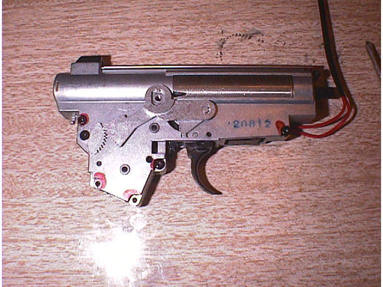
To
align the gears and levers on the other side, you can find on the
left and below three images that show what you should have. Basically,
with the black plastic rack at it's maximum extent (pulled out all
the way) the opposing lever on the other side should also, in turn,
be at its maximum extent.
In this position,
the fire-slect elver is in 'Full-Auto' mode
In this position,
the fire-select lever is in 'Safe' mode
When you put the gearbox
back into the receiver housing, you should make sure that you do not pinch
the red wires. There is a gully cut into the plastic for them on one side
of the gearbox - see image to the right.
You'll find that if
you have the cables in the wrong place, the top cover (that covers the
battery) will not go on properly.
When everything is
back together you should have a pile of spare parts,
I'd recommend putting
them back in the Systema box for safekeeping, you may need them in the
future.
When you go to fire the
rifle for the first time, I'd recommend firing a few shots, to ensure everything
is ok, rather than blasting away on full auto. If you have (for some reason)
got a problem in the motor/gearbox, the fuse in the stock will blow -
this is an indication of something being jammed that causes the motor to either
be put under excessive strain, or to not turn at all. If this happens, strip
the rifle back down to the gearbox, crack it open, and have a look, as you've
got something fundamental wrong inside, like a gear out of place.